The Synchro Transmitter Receiver Trainer from AGN Enterprises is an educational control systems and electrical engineering laboratory trainer designed to demonstrate the construction, working principle, angular position transmission, synchronization, and error characteristics of a synchro transmitter-receiver pair.
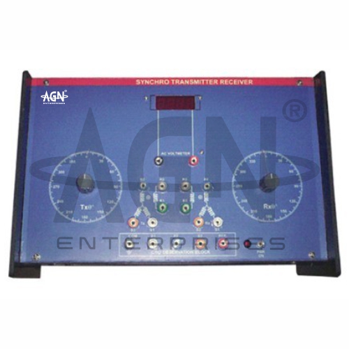
The illustrated trainer features two calibrated angular dials with manually adjustable shafts, clearly marked electrical terminals, a central indication section, and a printed experimental panel. This arrangement allows students to set an angular position at the transmitter, observe the corresponding receiver position, and investigate how synchro systems transmit mechanical angular information electrically.
The trainer provides practical experience with synchro systems, position transmission, electromagnetic induction, control transformers, angular displacement, error measurement, and servo-control fundamentals.
It is suitable for control systems laboratories, electrical engineering laboratories, electronics and instrumentation departments, engineering colleges, universities, polytechnics, and technical training institutes.
The primary aim is:
To study the operation and characteristics of a synchro transmitter and receiver system.
Students can also investigate:
Angular Position Transmission
Synchro Transmitter Operation
Synchro Receiver Operation
Synchronization
Position Error
Rotor and Stator Relationships
Electrical Position Control
Servo-System Fundamentals
A synchro is an electromechanical device used to transmit angular-position information electrically from one location to another.
A basic synchro system can consist of a transmitter and receiver. When the transmitter shaft changes position, corresponding electrical signals appear in its stator windings.
The receiver responds to these signals and rotates toward a corresponding angular position.
Therefore, synchros provide a practical method for remote indication and transmission of shaft position.
The synchro transmitter converts mechanical angular displacement into a set of electrical signals.
When students rotate the transmitter shaft, the relationship between its rotor magnetic field and stator windings changes. Consequently, the voltages associated with the stator terminals change according to rotor position.
These position-dependent electrical quantities carry information about the transmitter shaft angle.
The synchro receiver converts the electrical information from the transmitter back into mechanical angular displacement.
When correctly interconnected, the receiver develops a torque that tends to align its shaft with the position represented by the transmitter signals.
Thus, the complete system performs:
Mechanical Position → Electrical Signals → Mechanical Position
A synchro operates on principles related to electromagnetic induction and transformer action.
An AC excitation applied to the rotor produces an alternating magnetic field. The relative position of the rotor with respect to the stator windings determines the voltages induced in those windings.
When the transmitter stator connects to the corresponding receiver stator, the receiver experiences electromagnetic torque whenever its rotor position differs from the transmitted position.
The receiver then tends to rotate toward the corresponding equilibrium position.
The rotor forms the rotating element of the synchro.
Its angular position determines the relationship between the excitation field and the stator windings. Therefore, changing the rotor angle changes the electrical representation of shaft position.
The trainer’s large calibrated dials make these angular changes easy to observe during practical work.
A typical synchro contains multiple stator windings arranged symmetrically around the rotor.
The electrical outputs associated with these windings depend on rotor position. Together, the stator signals provide enough information to represent the shaft angle.
Students can therefore study how several AC quantities work together to transmit angular-position information.
The main experiment demonstrates remote angular-position transmission.
First, students establish the required transmitter-receiver connections. Next, they set the transmitter shaft to a selected angle.
The receiver responds and moves toward the corresponding position. Students can then compare the transmitter and receiver dial readings.
Repeating the procedure for several angular positions allows students to study the accuracy and behavior of the system.
When the transmitter and receiver indicate corresponding angular positions, the system is considered synchronized for the selected reference convention.
If students rotate the transmitter, the receiver follows the changing position.
This experiment provides a clear mechanical demonstration of how electrical signals can communicate positional information between separated devices.
The difference between the transmitter position and the corresponding receiver position can be described as an angular error.
In simplified form:
θₑ = θₜ − θᵣ
where:
θₑ = Error angle
θₜ = Transmitter angle
θᵣ = Receiver angle
Students can record this error for different shaft positions and analyze the tracking performance of the experimental system.
When the transmitter and receiver positions differ, the electrical conditions in the interconnected synchros produce a torque that tends to reduce the positional difference.
As the receiver approaches its corresponding equilibrium position, the effective error decreases.
Therefore, the experiment introduces students to the important control-system concept of error-dependent corrective action.
The illustrated trainer provides two prominent graduated circular dials.
These dials allow students to set and compare transmitter and receiver angular positions directly.
Moreover, the large scale markings make the experiment suitable for both individual laboratory work and instructor demonstrations.
The front panel includes multiple color-coded electrical terminals for the transmitter, receiver, excitation, and associated experimental connections.
Students can connect the system according to the prescribed circuit and observe how different terminal relationships affect operation.
The clearly organized panel also helps students understand the electrical connections between the two synchro units.
Students can take readings at several transmitter positions and compare them with the corresponding receiver positions.
They can then prepare an observation table or plot suitable characteristics, such as:
Receiver Angle versus Transmitter Angle
and, where required:
Error Angle versus Transmitter Angle
These results help students evaluate the positional relationship experimentally.
A typical experiment involves:
Students should follow the specific operating instructions supplied with the trainer.
Students can use the Synchro Transmitter Receiver Trainer to:
Synchro principles are closely related to position measurement and servo-control systems.
The trainer helps students understand how a mechanical position can be represented electrically and reproduced at another location.
Therefore, the experiment provides useful preparation for studying:
Servo Mechanisms
Position Control
Feedback Systems
Control Transformers
Error Detection
Electromechanical Control
The trainer combines concepts from several electrical engineering subjects, including:
AC Circuits
Transformers
Electrical Machines
Electromagnetic Induction
Instrumentation
Control Engineering
Consequently, it provides a useful multidisciplinary practical experiment.
Position sensing and transmission play an important role in instrumentation and automation.
The synchro experiment demonstrates a classical electromechanical method for transmitting angular information. This helps students understand the development of position-measurement technologies and the principles behind remote indication systems.
The trainer helps students understand:
Synchro Transmitters
Synchro Receivers
Angular Displacement
Position Transmission
Electromagnetic Induction
Synchronization
Error Angle
Corrective Torque
Servo Systems
Control Engineering
Furthermore, students can directly observe the relationship between an electrical control phenomenon and mechanical shaft movement.
The shown apparatus includes:
Exact excitation voltage, operating frequency, synchro specifications, angular resolution, electrical ranges, and accessories may vary according to the supplied model.
Students should check all transmitter, receiver, and excitation connections before switching on the apparatus.
They should use only the specified AC excitation and avoid short-circuiting the stator or rotor terminals. Furthermore, students should rotate the synchro shafts smoothly without applying excessive mechanical force.
Users should switch off the supply before altering connections whenever required by the laboratory procedure.
Users should keep the trainer panel, terminals, angular scales, and mechanical controls clean and dry.
They should rotate the shafts gently and avoid impact or excessive force. In addition, users should protect the apparatus from moisture, dust, excessive electrical input, and mechanical damage.
After completing the experiment, students should switch off the supply and store the trainer in a clean, dry laboratory environment.
The Synchro Transmitter Receiver Trainer is suitable for:
AGN Enterprises supplies Synchro Transmitter Receiver Trainers, DC Servomotor Trainers, Stepper Motor Controllers, control-system trainers, instrumentation equipment, and electrical engineering laboratory apparatus.
Furthermore, our educational trainers support control engineering, instrumentation, electrical machines, automation, electronics, and practical engineering education.