The Digital Multimeter Trainer from AGN Enterprises is an educational electronics and electrical laboratory trainer designed to demonstrate the working principles, functional sections, measurement techniques, and applications of a digital multimeter (DMM).
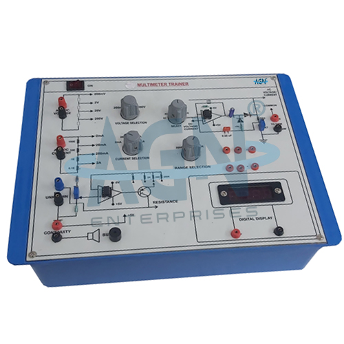
The illustrated trainer provides a large, clearly labeled experimental panel with circuit sections, rotary controls, test terminals, electronic components, signal paths, and an integrated digital display. Students can study how a digital multimeter processes electrical quantities and converts them into readable numerical measurements.
The trainer provides hands-on experience with voltage measurement, current measurement, resistance measurement, signal conditioning, analog-to-digital conversion, display circuits, and electronic instrumentation.
It is suitable for electronics laboratories, electrical engineering laboratories, instrumentation laboratories, engineering colleges, universities, polytechnics, ITIs, vocational institutes, and technical training centers.
The primary aim is:
To study the construction, working principle, functional blocks, and measurement techniques of a digital multimeter.
Students can also study:
DC Voltage Measurement
AC Voltage Measurement
Current Measurement
Resistance Measurement
Signal Conditioning
Analog-to-Digital Conversion
Digital Display
Electronic Instrumentation
A Digital Multimeter (DMM) is an electronic measuring instrument used to measure several electrical quantities with a numerical display.
Depending on its design, a digital multimeter can measure quantities such as:
Voltage
Current
Resistance
Some multimeters may also provide additional functions such as continuity, diode testing, capacitance, frequency, and temperature measurement.
The trainer focuses on helping students understand how these measurements take place inside a digital measuring system.
A digital multimeter converts an electrical input into a form that its electronic measurement circuit can process.
First, the selected measurement section conditions the input signal. Next, the instrument converts the conditioned analog signal into digital information through an analog-to-digital conversion stage.
Finally, the display section presents the measured quantity as a numerical value.
Thus, the basic measurement chain can be represented as:
Input → Range/Protection Circuit → Signal Conditioning → A/D Conversion → Digital Processing → Display
For DC voltage measurement, the input voltage passes through a suitable attenuator or voltage-divider network.
The divider reduces higher input voltages to a level compatible with the measurement electronics.
If:
Vᵢ = Input voltage
Vₘ = Voltage applied to the measuring circuit
then the relationship depends on the selected divider ratio.
Students can study how different measurement ranges allow the same digital measurement section to handle different input voltage levels.
An AC voltage changes magnitude and polarity with time. Therefore, the multimeter must process the alternating signal before producing a digital reading.
The AC measurement section typically conditions and converts the input into a suitable representation for measurement.
This experiment helps students understand the difference between DC and AC voltage measurement paths.
A digital multimeter commonly measures current by passing it through a known low-value shunt resistance.
The resulting voltage drop is:
V = IR
where:
V = Voltage across the shunt
I = Current being measured
R = Shunt resistance
The electronic measurement section measures this voltage and determines the corresponding current.
Therefore, the trainer demonstrates how an instrument can convert current into a measurable voltage.
For resistance measurement, the multimeter applies a controlled electrical condition to the unknown resistance and measures the resulting electrical response.
Using Ohm’s law:
R = V / I
where:
R = Unknown resistance
V = Measured voltage
I = Known or measured current
Students can therefore understand how a digital instrument determines an unknown resistance electronically.
The trainer reinforces the fundamental relationship:
V = IR
where:
V = Voltage
I = Current
R = Resistance
Voltage, current, and resistance measurement form the core functions of a standard multimeter. Consequently, this trainer provides an effective practical platform for studying Ohm’s law alongside electronic instrumentation.
Different electrical quantities can vary over a wide range.
Therefore, a multimeter uses suitable range-selection and signal-conditioning circuits to bring the input quantity within the operating range of its measuring electronics.
The trainer allows students to study the role of these circuits and understand why correct range selection is important during electrical measurements.
The input attenuator reduces an input voltage by a known ratio.
For a simple resistive divider:
Vout = Vin × R₂ / (R₁ + R₂)
This principle allows a digital multimeter to measure voltages larger than the direct input range of its analog-to-digital converter.
Students can relate this basic circuit to practical voltage measurement.
Before analog-to-digital conversion, the input signal may require conditioning.
Depending on the measurement function, signal conditioning can involve:
Attenuation
Amplification
Rectification
Filtering
Current-to-Voltage Conversion
Resistance-to-Voltage Conversion
The trainer helps students understand why different electrical quantities require different input circuits.
The Analog-to-Digital Converter (ADC) forms an important part of a digital multimeter.
It converts the conditioned analog electrical quantity into digital information that the display circuitry can use.
Therefore, the ADC acts as the link between analog electrical measurements and the numerical digital display.
The illustrated trainer includes an integrated digital display.
The display allows students to observe the final output of the measurement system directly. Moreover, students can trace the functional stages from the input terminals through the measurement circuitry to the displayed result.
This approach makes the internal operation of a digital multimeter easier to understand.
The trainer panel contains a clearly printed functional circuit layout.
Students can follow the signal path and identify the various stages involved in digital multimeter operation.
The large educational layout also helps instructors explain circuit operation during classroom demonstrations.
The trainer provides multiple accessible test terminals and experimental connection points.
These allow students to investigate selected circuit sections and make the connections required for prescribed experiments.
As a result, students gain more practical insight than they would by studying a sealed commercial multimeter alone.
Digital measurement depends on several factors, including:
Therefore, the trainer can also introduce students to practical concepts of accuracy, resolution, and measurement error.
Resolution represents the smallest change in an input quantity that an instrument can meaningfully display or distinguish.
A digital display with more usable digits can generally provide finer numerical indication, although display resolution alone does not determine overall measurement accuracy.
This distinction provides an important lesson in electronic instrumentation.
A voltmeter should have sufficiently high input impedance so that it draws minimal current from the circuit under test.
Students can therefore study the concept of loading effect and understand why input impedance matters in voltage measurements.
This concept is important when measuring sensitive or high-resistance electronic circuits.
Depending on the supplied configuration, students can perform experiments such as:
The exact experiments depend on the trainer configuration supplied.
Students can use the Digital Multimeter Trainer to:
The trainer helps students understand:
Voltage
Current
Resistance
Ohm’s Law
Voltage Dividers
Shunt Resistors
Signal Conditioning
Analog-to-Digital Conversion
Digital Displays
Measurement Accuracy
Electronic Instrumentation
Furthermore, the exposed educational layout allows students to understand the functional stages that remain hidden inside an ordinary handheld digital multimeter.
The Digital Multimeter Trainer provides practical training in:
Analog Electronics
Digital Electronics
Electronic Measurements
Instrumentation
Circuit Testing
Signal Processing
Therefore, it provides a useful foundation for students before they progress to more advanced measurement instruments.
Digital multimeters are among the most widely used instruments in electrical engineering.
Students use them for circuit testing, component measurement, maintenance, troubleshooting, and experimental verification.
Consequently, understanding the internal measurement principles helps students use digital multimeters more effectively in later laboratory and engineering work.
The trainer is particularly useful for introducing:
Measurement Systems
Signal Conversion
Input Conditioning
Digital Measurement
Instrument Resolution
Accuracy
Calibration Concepts
Thus, the apparatus provides a practical introduction to electronic instrumentation.
The shown apparatus includes:
Exact measurement ranges, display resolution, input limits, accuracy, power requirements, circuit facilities, and accessories may vary according to the supplied model.
Students should select the correct measurement function and range before applying an electrical input.
Furthermore, users should never exceed the specified voltage or current limits. Current measurement connections require particular care because incorrect connections can produce a short circuit.
Students should switch off the experimental circuit before changing connections whenever the laboratory procedure requires it.
Users should keep the trainer panel, display, terminals, switches, and controls clean and dry.
They should insert connecting leads carefully and avoid excessive force on terminals. Moreover, users should protect the trainer from overvoltage, short circuits, moisture, dust, and mechanical impact.
After completing experiments, users should switch off the equipment and store it in a clean, dry laboratory environment.
The Digital Multimeter Trainer is suitable for:
AGN Enterprises supplies Digital Multimeter Trainers, electronic measurement trainers, instrumentation equipment, analog and digital electronics trainers, electrical laboratory apparatus, and engineering educational systems.
Furthermore, our training equipment supports practical electronics education, electrical engineering, instrumentation studies, vocational training, and technical skill development.