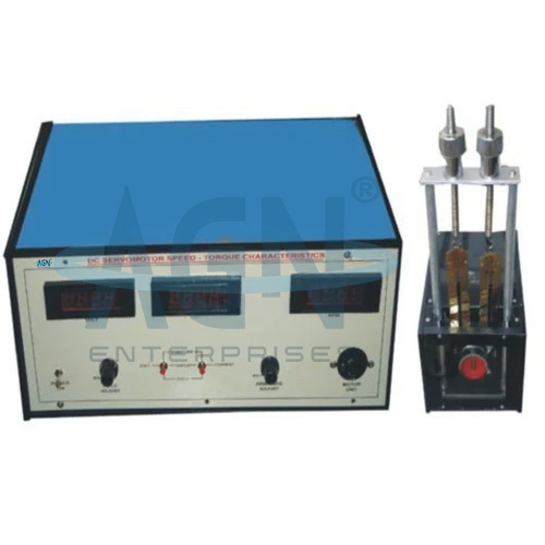
The Speed Torque Characteristics of DC Servomotor apparatus from AGN Enterprises is an educational electrical and control engineering laboratory setup designed to study the relationship between speed, torque, and operating conditions of a DC servomotor.
The illustrated setup consists of a main electronic control and measurement unit with digital displays and adjustment controls, along with a separate DC servomotor loading assembly. Students can vary the motor operating conditions, apply mechanical load, observe speed and torque, and plot the characteristic curves.
The experiment provides practical knowledge of DC servomotor operation, electromechanical energy conversion, motor loading, speed regulation, torque development, and control-system actuators.
It is suitable for control systems laboratories, electrical engineering laboratories, electronics laboratories, instrumentation departments, engineering colleges, universities, polytechnics, and technical training institutes.
The primary aim is:
To study and plot the speed-torque characteristics of a DC servomotor.
Students can also investigate:
Motor Speed
Developed Torque
Load Characteristics
Speed Regulation
Armature Control
Servomotor Performance
Electromechanical Characteristics
A DC servomotor is a DC motor designed for applications requiring controlled mechanical motion.
In a servo system, the motor converts an electrical control signal into mechanical rotation. Therefore, parameters such as speed, torque, response, and controllability play an important role in overall system performance.
DC servomotors commonly appear in laboratory studies of automatic control, position control, speed control, robotics, instrumentation, and electromechanical systems.
A DC motor develops torque when current flows through conductors located in a magnetic field.
The electromagnetic torque is approximately proportional to armature current when the magnetic flux remains constant:
T ∝ ΦIₐ
or:
T = KₜΦIₐ
where:
T = Developed torque
Kₜ = Torque constant
Φ = Magnetic flux
Iₐ = Armature current
Therefore, increasing armature current generally increases the developed motor torque under appropriate operating conditions.
The speed of a DC motor depends on the applied armature voltage, armature resistance, current, and magnetic flux.
A commonly used relationship is:
N ∝ (V − IₐRₐ) / Φ
where:
N = Motor speed
V = Applied armature voltage
Iₐ = Armature current
Rₐ = Armature resistance
Φ = Magnetic flux
Consequently, an increase in mechanical load usually increases armature current and can reduce motor speed.
The speed-torque characteristic describes how the rotational speed of the servomotor changes as its mechanical torque changes.
Students first operate the motor under a low-load or no-load condition. Next, they gradually increase the load and record the corresponding speed and torque values.
They can then plot:
Speed (N) versus Torque (T)
The resulting graph provides a clear representation of the motor’s mechanical performance.
The illustrated setup includes a separate motor and loading arrangement that allows students to apply controlled mechanical loading.
As the load increases, the servomotor must develop additional torque to maintain rotation.
Students can record the relevant measurements at several load conditions. Therefore, they can investigate the relationship between motor torque and speed experimentally.
The main unit includes digital indication for convenient experimental observations.
Students can monitor the motor speed while changing the load or electrical input conditions. They can then record the speed for each corresponding torque value.
This approach simplifies data collection and makes it easier to construct the speed-torque characteristic curve.
The separate mechanical assembly provides a method for applying load to the servomotor.
Students can vary the load progressively and observe how the motor responds. As load torque increases, the motor operating point changes.
Therefore, the loading mechanism allows students to investigate practical motor behavior rather than only theoretical equations.
At or near the no-load condition, the motor requires relatively little torque to overcome its own mechanical losses.
Consequently, its speed generally approaches the higher end of its operating range for the selected input condition.
Students can use this initial reading as one point on the speed-torque characteristic.
As students increase the mechanical load, the motor must produce more torque.
For a typical DC motor under fixed operating conditions, increased torque requires increased armature current. The additional internal voltage drop then contributes to a reduction in motor speed.
Therefore, the speed-torque curve commonly shows speed decreasing as torque increases.
If the load becomes sufficiently large, the motor may approach a stall condition, where rotational speed falls toward zero.
At stall, the motor can draw substantial current. Therefore, students should not intentionally hold the motor in a stalled condition unless the experimental procedure and apparatus specifically permit it.
The specified current and loading limits should always be observed.
The speed of a suitable DC servomotor can be influenced by changing the armature voltage.
Students may compare motor characteristics under different permitted voltage conditions where the trainer supports this function.
As a result, they can understand how electrical input affects mechanical output.
A servomotor commonly acts as the final control element or actuator in an electromechanical control system.
The motor receives an electrical control signal and produces mechanical movement.
Therefore, studying its speed-torque characteristics helps students understand how actuator limitations and loading conditions influence the performance of practical control systems.
Students can prepare a graph from the experimental observations with:
Torque on the horizontal axis
and
Speed on the vertical axis
The curve allows students to analyze how speed changes with mechanical loading.
Furthermore, they can compare experimental observations with the expected theoretical characteristics of a DC servomotor.
A typical experiment follows these steps:
The exact procedure should follow the instructions supplied with the apparatus.
Students can use the Speed Torque Characteristics of DC Servomotor apparatus to:
The experiment is particularly useful for students studying automatic control systems.
Servomotors provide controlled motion in many systems. Therefore, their mechanical characteristics influence accuracy, response, stability, and load-handling capability.
The apparatus helps students connect motor theory with practical control-system applications.
The trainer supports practical study of:
DC Machines
Motor Characteristics
Torque Production
Speed Control
Motor Loading
Electromechanical Energy Conversion
Electrical Drives
Consequently, the apparatus is useful for both electrical machines and control engineering laboratories.
DC servomotors also play an important role in instrumentation and automation.
Students can relate this experiment to applications involving:
Positioning Systems
Automatic Machinery
Robotics
Process Control
Industrial Automation
Motion Control
Servo Mechanisms
Thus, the experiment provides a foundation for more advanced actuator and control-system studies.
The shown setup includes:
Exact motor ratings, speed range, torque range, supply voltage, measurement resolution, control ranges, and accessories may vary according to the supplied model.
The apparatus helps students understand:
DC Motor Theory
Speed-Torque Relationship
Motor Loading
Armature Current
Back EMF
Torque Production
Speed Regulation
Servo Actuation
Control Engineering
Experimental Graph Plotting
Moreover, students gain practical experience in recording motor performance data and interpreting characteristic curves.
Students should check all electrical and mechanical connections before switching on the apparatus.
They should increase the load gradually and remain within the specified operating limits. Furthermore, users should avoid prolonged operation at excessive current or near stall conditions.
Students should keep hands, clothing, and loose objects away from moving motor and loading components during operation.
Users should keep the trainer, motor assembly, controls, and terminals clean and dry.
The motor shaft and loading mechanism should rotate freely without unnecessary obstruction. In addition, users should inspect electrical leads and mechanical connections periodically.
After completing the experiment, students should reduce the load, switch off the supply, and store the equipment in a clean and dry laboratory environment.
The Speed Torque Characteristics of DC Servomotor apparatus is suitable for:
AGN Enterprises supplies DC servomotor trainers, control-system trainers, electrical machine apparatus, motor characteristic setups, instrumentation trainers, and engineering laboratory equipment.
Furthermore, our educational systems support control engineering, electrical machines, electronics, instrumentation, automation, and practical engineering education.