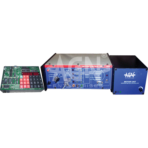
The Stepper Motor Controller with Microcontroller from AGN Enterprises is an educational electronics and embedded-systems laboratory trainer designed to study the control, interfacing, direction, speed, and stepping operation of a stepper motor using a microcontroller.
The illustrated experimental system consists of a microcontroller development unit, stepper motor controller/interfacing trainer, and motor module. The clearly arranged educational setup allows students to understand how digital commands generated by a microcontroller operate a stepper motor through suitable driver and interface circuitry.
The trainer provides hands-on experience with microcontroller programming, motor interfacing, sequential excitation, step-angle control, clockwise and anticlockwise rotation, speed variation, and embedded motion-control principles.
It is suitable for microcontroller laboratories, embedded-systems laboratories, electronics engineering departments, electrical engineering laboratories, instrumentation courses, robotics laboratories, engineering colleges, universities, polytechnics, and technical institutes.
The primary aim is:
To interface and control a stepper motor using a microcontroller.
Students can also study:
Stepper Motor Operation
Microcontroller Interfacing
Clockwise Rotation
Anticlockwise Rotation
Speed Control
Step Control
Digital Pulse Sequences
Motor Driver Circuits
Embedded Motion Control
A stepper motor is an electromechanical device that converts a sequence of electrical input pulses into discrete angular movements.
Unlike a conventional motor that can rotate continuously when energized, a stepper motor advances through defined angular increments called steps.
Therefore, the number and sequence of control pulses can determine the motor’s angular movement.
A stepper motor contains multiple windings or phases. The controller energizes these phases in a specific sequence to produce a rotating magnetic field.
The rotor responds to this changing magnetic field by moving from one stable position to the next.
Therefore:
Electrical Pulse Sequence → Phase Excitation → Magnetic Field Change → Rotor Step
By repeatedly generating the required excitation sequence, the microcontroller produces controlled rotation.
The microcontroller acts as the programmable control element of the experimental system.
A program stored or executed by the controller generates the digital sequence required for motor operation. The interface and driver circuitry then provides suitable signals to the motor windings.
Students can modify the control logic to investigate different motor operating conditions.
Thus, the trainer connects microcontroller programming with a real electromechanical output device.
A microcontroller generally cannot drive a stepper motor winding directly because the motor may require more current or voltage than a logic output can safely provide.
Therefore, a driver/interface stage is placed between the microcontroller and the motor.
The functional sequence becomes:
Microcontroller → Driver / Interface Circuit → Stepper Motor
This arrangement helps students understand an important principle of embedded-system hardware design.
The step angle represents the angular movement of the motor shaft for each full step.
If a motor requires N full steps for one complete revolution:
Step Angle = 360° / N
For example, the actual step angle depends on the construction and specification of the supplied motor.
Students can use this relationship to determine the number of steps required for a desired angular displacement.
One of the major advantages of a stepper motor is its ability to perform controlled incremental movement.
If the motor step angle is α and the controller applies n steps, the ideal angular displacement is:
θ = nα
where:
θ = Angular displacement
n = Number of steps
α = Step angle
Consequently, students can program the motor to rotate through a selected number of steps or revolutions.
The direction of rotation depends on the order in which the motor phases receive excitation.
By generating the appropriate sequence, the microcontroller can rotate the motor in the clockwise direction.
Students can observe the output sequence and relate it directly to mechanical shaft rotation.
Reversing the phase-excitation sequence reverses the rotating magnetic-field progression.
As a result, the motor rotates in the anticlockwise direction.
Therefore, students can learn that motor direction can be controlled through software without mechanically reversing the motor.
Stepper motor speed depends primarily on the rate at which the controller supplies step commands.
Increasing the step frequency generally increases rotational speed within the motor and load’s permissible operating region.
For a full-step system:
Speed (rpm) = 60f / N
where:
f = Step frequency in steps per second
N = Number of full steps per revolution
Thus, changing the program delay or pulse frequency provides a straightforward way to study digital speed control.
In full-step operation, the controller advances the motor through its normal full angular increments according to the selected excitation sequence.
Students can study the sequence of phase energization and observe the corresponding shaft movement.
The exact excitation table depends on the type and wiring of the supplied stepper motor.
Where supported by the supplied motor and controller, half-step operation uses an expanded excitation sequence to create intermediate rotor positions.
This reduces the angular movement per command compared with normal full stepping.
Therefore, half stepping can provide finer position resolution.
The motor driver provides the electrical interface between the low-power microcontroller signals and the stepper motor.
Its functions can include:
Current Switching
Phase Selection
Logic Interfacing
Motor Protection
Signal Amplification
Understanding this stage helps students learn why practical embedded systems require interface electronics between processors and actuators.
Stepper motor control depends on an ordered sequence of logic states.
The microcontroller repeatedly outputs these states through its digital ports. Each new state changes the energized motor phase or phase combination and causes the rotor to move.
Students can therefore observe a direct relationship between binary digital outputs and mechanical motion.
The experiment introduces several useful programming concepts, including:
Digital Output Control
Loops
Time Delays
Sequence Generation
Direction Control
Step Counting
Speed Variation
Port Programming
Consequently, the apparatus provides practical programming experience rather than limiting microcontroller study to LEDs and switches.
The illustrated setup includes:
Exact microcontroller family, motor type, step angle, operating voltage, driver circuit, software environment, speed range, and accessories may vary according to the supplied configuration.
A typical experiment involves:
Students should follow the operating instructions supplied with the trainer.
Students can use the Stepper Motor Controller with Microcontroller to:
Stepper motors are widely used where controlled incremental movement is required.
The trainer introduces principles relevant to:
Embedded Systems
Automation
Robotics
Mechatronics
Positioning Systems
Computer-Controlled Machinery
Instrumentation
Therefore, the experiment provides a useful bridge between embedded programming and physical motion control.
Robotic systems frequently require precise control of mechanical movement.
Stepper motors can provide controlled rotational increments for suitable positioning mechanisms. Consequently, understanding stepper motor interfacing helps prepare students for experiments involving robotic arms, positioning platforms, and automated mechanisms.
The trainer helps students understand:
Microcontrollers
Stepper Motors
Digital Interfacing
Motor Drivers
Pulse Generation
Sequential Logic
Speed Control
Direction Control
Position Control
Embedded Programming
Furthermore, students can immediately observe how changes in software affect the physical behavior of the motor.
Students should check the motor wiring and power connections before switching on the trainer.
They should not connect motor windings directly to microcontroller I/O pins unless the supplied circuit specifically provides the required driver interface.
Furthermore, users should operate the motor within its specified voltage and current limits. Excessive mechanical loading should also be avoided because it may cause missed steps or motor heating.
Users should keep the microcontroller trainer, controller unit, motor module, terminals, and connecting accessories clean and dry.
They should make connections carefully and switch off the relevant supply before altering wiring when required by the experimental procedure.
After completing the experiment, users should stop the program where appropriate, switch off the equipment, and store all modules safely.
The Stepper Motor Controller with Microcontroller is suitable for:
AGN Enterprises supplies Stepper Motor Controllers, Microcontroller Trainers, Motor Interfacing Kits, Embedded Systems Trainers, Robotics Laboratory Equipment, Electronics Trainers, and Engineering Educational Systems.
Furthermore, our laboratory trainers support microcontroller programming, embedded-system development, automation, robotics, electronics engineering, and practical technical education.